Honeywell Wiring Diagram 3 Port Valve Wiring Diagram

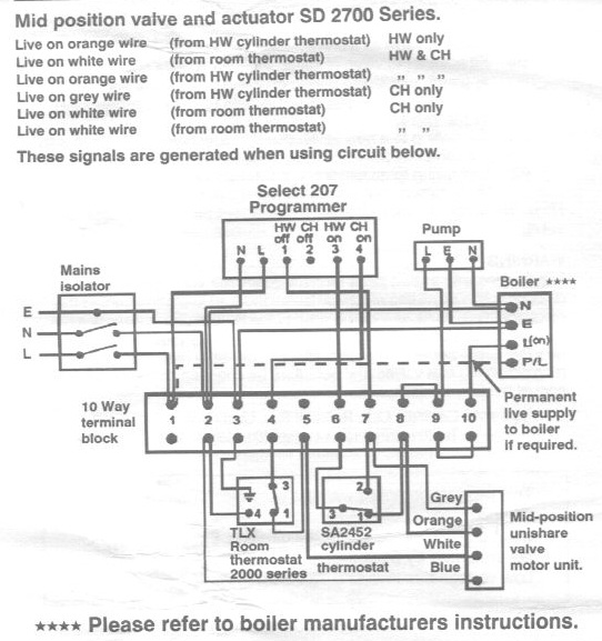
Valve wiring configuration is: Brown = Motor open Blue = Neutral Green/Yellow = Earth Notes: a Wiring diagram shows connections to a programmer with separate control of heating and hot water. b If single channel time clock is used, connect switched live from time clock to terminal 4 or 6 at junction box, then link terminal 4 to terminal 6 with.
Honeywell Wiring Diagram 3 Port Valve Wiring Diagram
Part 4 in the heating wiring series covers how the 3 port mid position valve works internally, allowing 3 separate positions from only 2 mains inputs.Website.
Unique Drayton 22mm Mid Position Valve Wiring Diagram diagram diagramsample diagramtemplate

This video covers the 3 port valve. In particular its position in a Y plan system. We also cover the basics of installing or replacing a three port valve or.
[47+] Wiring Diagram For Honeywell 3 Port Valve, Y Plan With Greenstar Worcester Boiler DIYnot

dcox Screwfix Select. Wiring is not my strong point. A customer with an open vented boiler has hot water but no heating. I suspect the danfoss 3 port valve. There are 4 wires: orange (switched live), grey (hot water off), brown & white (heating on) and blue (neutral). I was expecting the orange to become live once the valve had moved to the.
Danfoss 2 Port Wiring Diagram Danfoss Vfd Wiring Diagram 2 Port Valve Wiring Diagram Cars
The wiring diagram is a crucial tool for installing and troubleshooting the Honeywell 3 Port system. It illustrates the electrical connections between the various components, such as the boiler, the valve, and the thermostat. The diagram typically includes color-coded wires and clearly labels the different terminals on the components.
Wiring Diagram For 3 Port Motorised Valve Danfoss Hsa3 3 Port Valve Actuator 087n658700 / 441
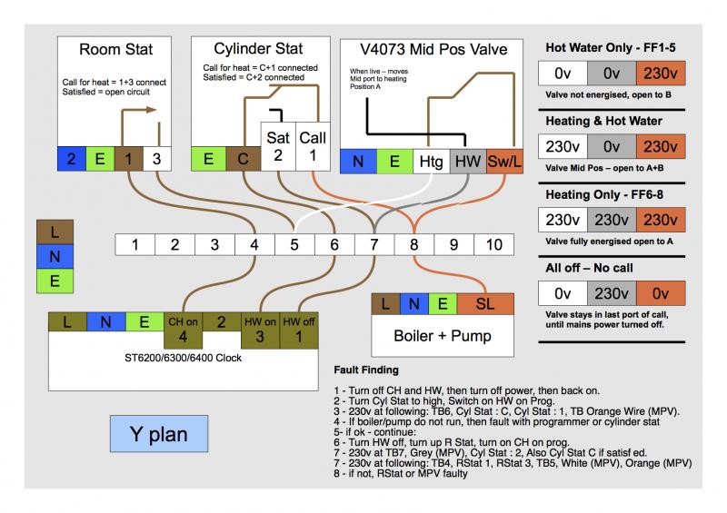
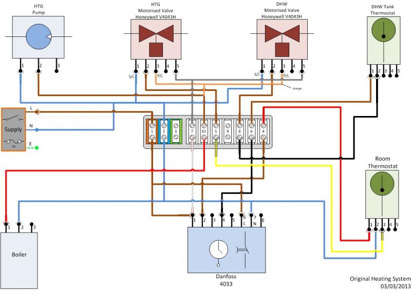
Operation - Hot water only. Power starts at terminal 3 (HW On) in the programmer. This passes via the wiring centre terminal 6 to the cylinder thermostat. If heat is required, power continues to terminal 8 in the wiring centre, and on to the boiler and pump. The valve is not powered at all, and the spring holds it in position B, so water from.
Sunvic Dm5601 Wiring Diagram Wiring Diagram
Honeywell 3 Port Valve Diagrams provide homeowners and contractors with an essential step in the process of installing a water or central heating system. This simple diagram, which outlines the connections between a valve, pipes, and other components, is used to make sure that the installation is secure and leak-free.
Wiring Diagram 3 Port Valve 26 3 Way Solenoid Valve Diagram 3 Port Valve Wiring Diagram
Page 1 Provides electrical output to boiler and/or pump APPLICATION The V4073A Valve has been designed to control the flow of water in domestic central heating systems, where both radiator and hot water cylinder circuits are pumped. It is typically suited for small OPTIONS to medium sized installations. Page 2 = CH only (port A open), 240V output on orange wire 240V in grey wire = Valve held.
Wiring Diagram For 3 Port Motorised Valve Danfoss Hsa3 3 Port Valve Actuator 087n658700 / 441
Electrical wiring for central heating systems.Part 3 in the series looks at Y plan wiring, a system which uses a single 3 port valve. This has one inlet and.
Drayton 3 Port Valve Wiring Diagram WiringDiagramPicture
Hive 3 Port Valve Wiring Diagrams provide a comprehensive overview of the installation and configuration of heating systems. With two-port valves, the wiring for the room thermostat, cylinder thermostat, and boiler are very straightforward and simple to understand. When it comes to wiring a three-port valve, however, there is a bit more complexity to consider.
️Drayton 2 Port Valve Wiring Diagram Free Download Goodimg.co

We show how to wire up a Y Plan System from scratch and how to replace and wire up the other components such as the 3 port valve, cylinder thermostat, pump a.
Central Heating How the mid posisiton Y plan 3 port valve works YouTube

The Honeywell V4073A three port, mid position, spring return valve, is a masterpiece of clever engineering. It manages to move to one of three positions using only a cheap non-reversible AC motor, a spring, a couple of micro-switches, a resistor and a diode, and act as a relay for the boiler into the bargain! However, it has obviously required.
Honeywell Wiring Diagram 3 Port Valve Diagram Mid Position Valve Wiring Diagram Full Version

Take a look through our current and legacy wiring diagrams. n n Uponor. Menu. Contact. Close. Uponor UK. Head Office Uponor UK The Pavillion. 3 Port Valve 3PV 1.0A wiring diagram. Wiring diagram for 3 Port Valve 3PV 1.0A. PDF 292 KB. View document Download document. Smatrix Wave Wiring Diagram with FLUVIA 15. Wiring diagram for Smatrix Wave.
MAYANG [7+] Reliance 2 Port Motorised Valve Wiring Diagram, [DIAGRAM] Honeywell 3 Port Valve

6 Dec 2020. #2. The mid position 3-Port motorised valve relies upon a 'HW off' signal to move it fully across to the heating only position. This signal comes from two places. The 'HW off' at the programmer [Hive dual channel terminal 1] and also the Hot water cylinder thermostat satisfied terminal.
Honeywell Wiring Diagram 3 Port Valve Wiring Diagram
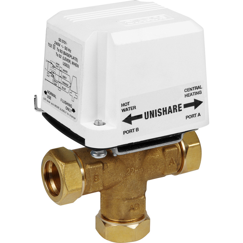
This is how the 3-port central heating valve works. The valve consists of a brass body with three compression fittings: one in and two out. Water flow is controlled by a rubber ball can block either outlet or take up a position which allows water to flow through both outlets. The position of the ball is controlled by a motor unit which is.
Honeywell 3 Port Valve Wiring Diagram / V4044C1288 Diverter valve 22mm 3 wire 3 port. Honeywell

Three port valve wiring is an essential part of any heating system that uses a three port valve. The three port valve is responsible for controlling the flow of water between the boiler, the central heating system, and the hot water cylinder.. electrical tape, a multimeter (for testing), and the wiring diagram specific to your valve model.